5.2 CirSeq inception
5.2.1 Basis for the search
After embracing the spiroid-frequency-space as a welcome alternative to rectilinear representations of the frequency-domain, the creation of a non-rectilinear representation of time was sought. More specifically, it was decided that a finite duration or period would be represented in a circular way; the data contents of that period would be cyclically looped, although that contents may itself change over time such that musical progression be possible through multiple cycles of the time-space. The data represented within this model would be for parameter control in a soundmaking system, rather than being audio data that could be directed to a DAC.
The spiroid-frequency-space is a representation that is very much based on polar-coordinates, and so – with the domain dichotomy described at §3.6.2 in mind – it seemed appropriate for a time-space representation to be created that, despite being of circular design, has its basis firmly upon cartesian-coordinates. Although this representation is being constructed with adherence to the cartesian grid, its non-rectilinearity is based on a clock-like angular motion for traversal of time, and so this conception of time-space has a polar aspect present at its core.
The CirSeq folder in the chapter5 directory of the portfolio contains CirSeq Inception.pdf (created October 2011) which details eleven illustrated steps of development of, and some notes pertaining to the background of, the CirSeq concept; below is a three step summary of how the concept is constructed as a geometrical progression.
5.2.2 A circle on a cartesian plane
With a cartesian grid of integer unit divisions as the basis of the time-space representation, a circle is drawn with a radius of one to represent a period of specific duration. This circle is, then, found to be touching integer coordinate points of the grid at four places.
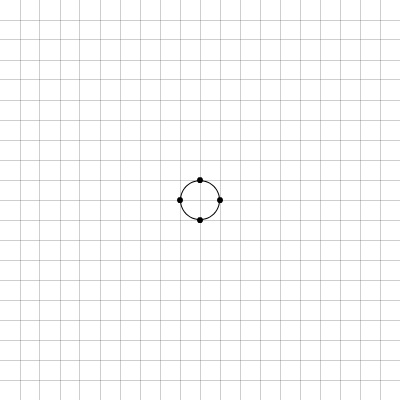
Figure 5.1: cirseq_thisis_01
Thus, the period represented by this circle on the time-space plane is immediately quantised to quarter divisions of its whole, and four equal durations are manifest between the points marked by the dots in Figure 5.1; if the direct path through these points is drawn, then a square (at 45 degrees of rotation relative to the orientation of the grid) is formed. The square formed by the quantisation of the first circle is shown in the centre of Figure 5.2 below.
5.2.3 Another circle on the plane
A second circle is then drawn on the grid, concentric to the first, and with a radius that is twice that of the first. It is important to note that each concentric circle is drawn on the time-space plane to represent the same period. As with the circle that has a radius of one cartesian-coordinate unit, this radius two circle is again found to only touch upon the grid at four integer coordinate points. Corresponding to the same four time-space angles that quarter the period represented by the radius one circle, these points are marked visually by a dot of the same type.
It is shown, in Figure 5.2, that on the straight lines that directly connect the four corner points that create the 45 degree square within the radius two circle, there is found another set of points that intersect with the cartesian-coordinate grid; these occur at the time-space angle that is mid-way along each of the four line segments: each has been marked with an 'x-dot'.
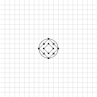
Figure 5.2: cirseq_thisis_02
5.2.4 Double and double again
After the radius two circle has been drawn, and those extra quantisation points found, the process of doubling the radius can be twice repeated: when the concentric circles of radius four and radius eight are drawn on the grid, the total number of grid-quantised points that are found to occur upon the 45 degree square line path inside each circle is also found to double for each doubling of the radius. Those two circles are shown in Figure 5.3 along with their 45 degree square line paths; 'open-dot' and 'square-dot' markings are used for the newly added time-space angle quantisation points that are introduced by the two new circles drawn.
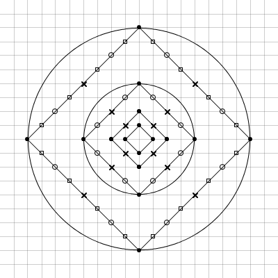
Figure 5.3: cirseq_thisis_03
Note that, along any square line path, while the linear distance between each adjacent quantisation point – or 'node' – is always the same (in the units of the grid, it is the square root of two), the duration of the period represented by that distance is dependant on the radius of the circle to which that path, and those nodes, belong. Whereas the notion of polar-coordinates on the spiroid-frequency-space equates angle to pitch-class and radius to octave-level, on the CirSeq time-space angle equates to temporal-phase and radius to temporal-resolution: a greater radius value creates more sub-divisions of time.
5.2.5 Common time
It will be apparent by now that my goal of designing a time-space representation that is based on the quantisation of a circle to the integer coordinates points of a cartesian grid has resulted in a literal reinventing of a very well known wheel: the scheme described above corresponds exactly to the common method rhythmic notation present in CMN; a sketch of that conformity is shown Figure 5.4.
If a radius three circle is drawn on the CirSeq time-space, then twelve equal divisions are found of the whole period (three nodes per quarter period), and with the parlance of CMN it can be said that these equate to triplet quavers; to then double from that to a circle of radius six is to find triplet semi-quaver divisions (six nodes per quarter period).
-.png)
Figure 5.4: 4n8n16n32nNotes
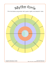
Although it had not been my intention to arrive at such a conclusion, the occurrence of this formation now seems inevitable for a time-space that is devised by this method of geometrical interaction between circles on the squares of a grid; the square line paths created produce multiples of four nodes per 'system',[n5.1] and it is used because the circle intersects at precisely four points.[n5.2] The resultant structure that has been found through the geometry explored can thus be directly related to crochets, quavers, and so on, but the geometrical reasoning for the progression of sub-divisions, described in my work above, is not so common: for the notes of CMN, sub-divisions of duration value are more usually depicted by a hierarchical tree-type structure that begins with two minims below a semibreve, and above four crotchets. Some circular representations closely resembling CirSeq have been identified: one in an educational worksheet by Susan Paradis (2008), see Figure 5.5 (this is, however, an abstract representation to aid cognition of theory, rather than a functional time-space traversed my angular motion); and another in two software applications for the Android platform (Google, n.d.) by One Man Band Studios S.A.S: both the bComposer Metronome and bComposer Rhythm apps (2013a, 2013b) use circular divisions in their GUIs that are akin to the CirSeq pattern, see Figure 5.6.
[n5.1] 'System' is the term used to describe the square line paths of node that are created within the concentric circles; it is, I now think, an unfortunate choice of word, but it will, nonetheless be encountered in the description below because it is coded into the software.
[n5.2] The circumference may, for larger radii, come close to (or maybe even touch) the cartesian-coordinate grid at other angles (especially if the radius was very large), but only those four quarter angles are present for every integer radius circle.
In contrast to those similarly constructed examples, above, there are also many instances of circular time-space representations that do not include the radius-resolution aspect of the polar-type traversal of time on the plane. Of the step sequencer interfaces that arrange their discrete steps in a closed loop, those that have only one track/path/system of steps/nodes are of less interest here. It does, however – given the amount of historical context provided elsewhere – seem appropriate to include some mention of The Circle Machine created by Raymond Scott in the 1950s: Bob Moog has written of Scott as an inspiration and friend, and it seems that Scott had been very secretive of his technological advancements in electronic music in those early years of its development as a field. The Circle Machine is now cited as one of (if not the) first electronic soundmaking sequencer systems (Winner, 2001, n.d.).[n5.3]
[n5.3] Pre-electronic examples of soundmaking sequencer technologies include disc and cylinder music-box mechanisms, and the 'player piano' mechanisms that are related to the Jacquard loom and from which comes the 'piano roll' metaphor that is now a commonplace paradigm for the visual representation of midi note-on and note-off events.
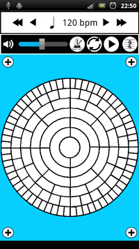
One example of a circular interface that does include concentric systems of step sequencing tracks is the Loopseque software (Casual Underground, n.d.) which has four concentric systems, each having sixteen steps, or nodes, that can be toggled on or off (Figure 5.7). In Loopseque, the polar aspect of radius has been implemented to provide access to four different samples or pitches of the 'instrument' for which that wheel is sequencing. The visual consequence of maintaining the number of divisions at different radii is that the size of the nodes is much smaller for that inner system compared to the outer.
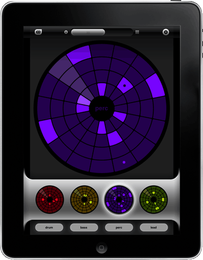
Figure 5.7: Loopseque_Wheel
The paradigm of mapping radius to pitch-class within a circular time-space representation is also seen in the GUI for the AlphaLive software that works with the AlphaSphere instrument (nu desine, n.d.); that 'circular sequencer interface' is illustrated in Figure 5.8 below. At first I thought the nodes of the systems were coloured light and dark to correspond to the keys of a piano for visual orientation within the 12TET pitch-space, but on closer inspection the twelve tracks seem more to just be alternating; where there is a keyboard layout within the GUI it has a set of twelve pitches highlighted blue, and this suggests that that is selecting the pitches that are mapped to the radial systems on the time-space.
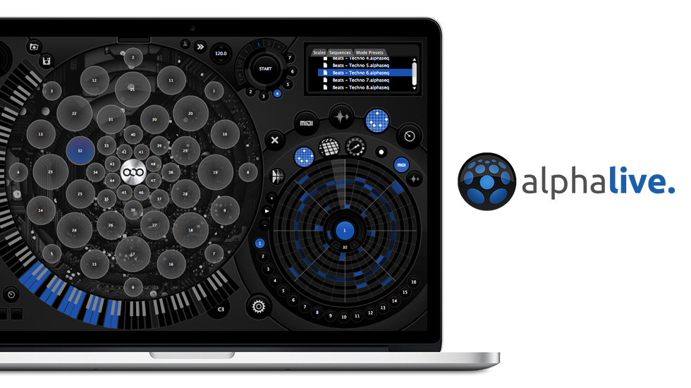
Figure 5.8: AlphaLive