4.4 Spiroid as an interface for input
Discussion is now directed to use of the spiroid-frequency-space concept as the basis for specifying frequencies as input to software.
Three examples from my work are provided: first is another proof of concept type patch, nRadii_sawOsc (§4.4.1); next (in §4.4.2) a spiroid based GUI widget is described; and the third example is an extension to the spiroidArc patch by which numbered frequency markers are placed upon the analysis display (§4.4.3).
The coiled presentation of a piano-keyboard type interface in the Magic Piano app by Smule Inc. (Hamilton et al., 2011, p. 61) is offered as an example a spiroid-like concept exhibited in software that has been released during the period of this project. Alignment of pitch-classes to angles in this input design, however, is only approximate, and the spiralling of the piano-keyboard is based on two octaves per turn (≈ 23 semitones per 360 degrees are seen in Figure 4.19).

Figure 4.19: Smule Magic Piano
4.4.1 nRadii
(4.4.1.a) nRadii_sawOsc overview
The 'n' in title of this piece is used in the sense of 'any number', as in, any number of radius lines to be placed with equiangular spacing on a spiroid-frequency-space representation. The nRadii folder in the chapter4 directory of the portfolio contains nRadii_sawOsc.maxpat (pictured in Figure 4.20) plus documentation of that patch.
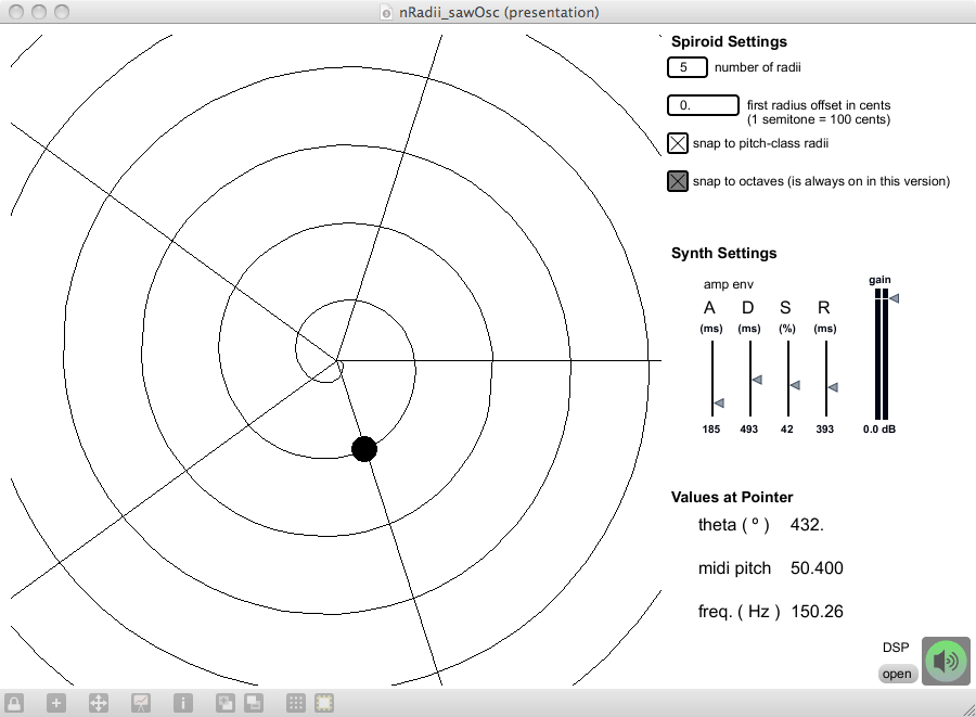
Figure 4.20: nRadii_sawOsc.maxpat
[…]
The nRadii_sawOsc work is a proof of concept patch that has a sawtooth waveform oscillator (thus the '_sawOsc') controlled my mouse interaction with a spiroid-frequency-space GUI. The patch will load in its presentation view showing the spiroid GUI to left of some settings above an information display reporting the value of the mouse pointer on the GUI in different units (theta, midi-pitch, and Hertz). At the top are spiroid settings where the number of radii to be placed upon the spiral is set; an offset value, in cents, can be used to adjust the angle of the first radius (see §(4.4.1.c), below, about angles in the version of spiroid). There is a toggle option for having the mouse controlled value selection on the GUI 'snap' to the currently displayed pitch-class radii. A second toggle, that is always on in this patch, brings attention to the fact that the input will always quantise to octave-level values that sit upon the curved continuum. The question of what might happen if we were to allow non-quantised octave-level values is significant, but discussion of that question would be in connection to synthesis experiments (involving granular approaches to octave shifting whilst maintaing pitch-class identity) that I chose to omit from this portfolio.
The test tone synthesiser has only the parameters of its fundamental frequency – set on the spiroid – and an (ADSR) amplitude envelope with attack time, decay time, sustain level, and release time being set by sliders. The mouse button acts as the attack and release trigger for the ADSR envelope.
(4.4.1.b) Construction of the nRadii GUI
As a developmental step beyond the spiroid-frequency-space work described in the previous sections of this chapter, there are a number of significant changes of method that can be seen to lead on directly to the works that follow. Examination of the spiroidArc patch described above will show that multiple lcd objects were used, with transparent backgrounds, to build up different layers of the display – the arcs are drawn to one, the histogram to another, and so on. In the nRadii work, jitter matrices are used for the spiral background, radii lines, and pointer spot layers that comprise the GUI; a jit.lcd object is used to draw to those matrices that are then combined into a single matrix for on screen display with a jit.pwindow object which then provides mouse interaction data for the system.
The spiroid-frequency-space equations – for converting between theta and midi-pitch values, given at the end of §4.1.4 – are used in this piece of software; Figure 4.22 shows where this happens in the mouse_interaction sub-patch: the theta value having been derived from the mouse coordinates on the GUI, which may or may not have been quantised to a radius line (please refer to the above mentioned documentation for details of that process).
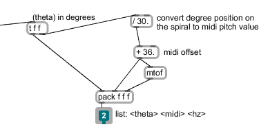
Figure 4.22: theta_to_midi
(4.4.1.c) Angular manifestation
The cartopol and poltocar objects, that are used in this piece, natively place the value zero angle at the three o'clock position; when using a midi-pitch offset value that is a multiple of twelve, the pitch-class of 'C' is placed at that angle. Rather than adjust the algorithm to move 'C' to the twelve o'clock position, as was done for previous implementations of the spiroid, it was decided that the native manifestation was perfectly acceptable. Critical reflection of the situation thus created reveals aesthetic support for the placement of pitch-class 'A' which is now found at twelve o'clock conceptual reference point of a clock face, it the angle from which minutes are counted; one may think also of how North is cardinal reference for magnetic compass points, and then of how 'A 440' is the standard reference point for mapping the midi-pitch scale to Hertz.
(4.4.1.d) A topic for NIME
Further work to nRadii system would appear to be relevant to the field of new interfaces for musical expression, typified by the annual conference of that name (NIME).[n4.18] Within the archive of that conference similar works can be found; a pitch-class circle was, for example, used by Lo?c Kessous (2002) as the basis for mapping the position of the stylus on 'the A6 Wacom graphire2 graphic tablet' to pitch-class, while octave-level was navigated either by button presses, or by crossing the 'start' of the circle to give the interface 'a boundless range'. An interesting feature of the pitch-class circle mapping in that work is the use of transfer functions across each 12TET semitone angle of the circle. Figures from that paper are included here as Figure 4.23, below; they show (Kessous, 2002, p. 114):[n4.19]
[n4.18] 'The International Conference on New Interfaces for Musical Expression […] started out as a workshop at the Conference on Human Factors in Computing Systems (CHI) in 2001.' (http://www.nime.org/, accessed 20131217).
[n4.19] The pitch-class-circle in this work by Loïc Kessous appears to have the lightness attribute of the HSL colour-space mapped to 12TET divisions of the circle, while the hue is constant.
“Portions de Camembert” representation of the fundamental frequency angular control [and]
Four examples for transfer function that can be used for fine-tuning (linear, sign (x)*x2, x3, x5).
[…] The transfer functions are designed to allow the user to have stable and efficient control of tonal pitch accuracy and force him or her to make a conceptual effort to have fine tuning variations.
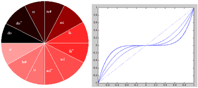
Figure 4.23: Kessous2002Mapping
4.4.2 A spiroid widget design
(4.4.2.a) A type of dial that is based on the spiroid
Both the spiroidArc display and the nRadii GUI are atemporal in their design: each is representing an instantaneous view of now in the frequency-domain (notwithstanding the paradoxical nature of that statement when the uncertainty principle is considered).
In §5.3, the working prototype of a time-space representation CirSeq Zero is described; sinusoidal oscillators are used within that work to make audible the divisions of time that are created by the visual representation. To control the frequencies and amplitudes of those sinusoids in time-space I created a spiroid-frequency-space widget, which is described here.
The spiroid widget works as a three-dimensional controller manifest on screen plane as similar to a dial type GUI element; whilst writing this document, the name 'spiroidial'[n4.20] has presented itself to encapsulate the concept. The spiroidial is conceptually descended from the spiroidArc in many ways. Each spiroidial on screen represents three constituent dimensions of a partial: pitch-class as angle, octave-level as radius, and amplitude as opacity. In both the spiroidArc design and the spiroidial the spiral curve of the frequency-domain continuum is not itself shown; this is in contrast to the input method exhibited in the nRadii system, described above, where the spiroid-frequency-space is explicitly mapped on a visible curve on screen. Within the interface of CirSeq Zero, for which the spiroidial was invented, spatial location on screen is representative of temporal data, and there are many spiroidial controls distributed within the GUI. Each spiroidial, therefore, specifies pitch-class and octave-level according to its own polar origin at the place where it is located on screen.
[n4.20] The word is a contraction of spiroid and dial; I thought to, perhaps, let the second 'i' be silent to put emphasis on the 'dial' at the end of the word, as in 'spiro-dial', but in practice I read the word as it appears.
(4.4.2.b) Mouse interaction with a spiroidial
There are two conventional methods by which a dial type widget on screen may be affected by mouse interaction: (1) after the mouse button is click on the dial – the mouse down (md) event – moving, or dragging, the mouse up or down will increase or decrease the value represented by the dial with the visual manifestation of angular change clockwise or anti-clockwise; it is common for the mouse pointer position on screen to be reset to where the md happened, after the mouse up (mu) event. (2) alternatively the mousing that happens between md and mu on the dial may be used to explicitly control the visual angle of the widget and thereby affect the value represented.
For the spiroidial widget, I chose to base the model of interaction upon the first (up/down) method, and extend this to the control of three discrete parameters with a spatio-visual metaphor. The metaphor – see Figure 4.24 below – evokes the operation of a manual transmission gearstick in a car: the md point on screen is comparable the neutral position of a gearstick, in that movement from there may optionally be left or right, before being forward or backward (up/down on screen) in order to affect the desired change in the system. The analogy is loose, however, because a manual transmission gearstick is used to access discrete values at each terminus. In contrast to that, the click-and-drag movement on a spiroidial widget uses the optional left/right stage of the action to select one of three parameter domains which will then be affect by relative change in proportion to the up/down movement.
To alter the amplitude value represented by a spiroidial, click and drag up/down; the opacity will change in response. To alter the pitch-class, click and then first drag to the left (to engage pitch-class control), and then drag up/down; the angle will be affected in the visual domain. To alter the octave-level, click and drag to the right and then up/down; the radius of the spiroidial will increase/decrease.
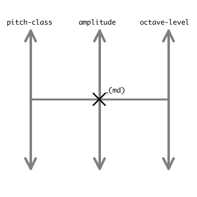
Figure 4.24: spiroidial_mouse_interaction
(4.4.2.c) Specific implementation of a concept archetype
The spiroidial concept has now been described as an archetype of a GUI element, but its only implementation in my work is as part of the CirSeq Zero system described below. The concept was developed in response to the challenge of wanting to specify frequencies and amplitudes at points in time-space. The implementation is thus deeply integrated to the CirSeq Zero system: there is no 'spiroidial abstraction' to be found, and that name was not used at the time of its programming.
There are no further examples of spiroidials being used in this project, but this is more the result of a change in approach imparted after the completion of the CirSeq Zero piece (see §5.3), as opposed to being an indication of a lack of potential. The concept may yet find use in future works, but if so then it would be likely that the radius to octave-level mapping would be reversed so that a larger radius would give a lower frequency in order to be more reflective of physical reality in which larger bodies tend to resonate at lower frequencies.
4.4.3 SpiroidArc plus sequencing
(4.4.3.a) Frequency markers
The SpiroidArc patch described in §4.3 was modified to include an implementation of 'numbered frequency markers': a set of up to nine points on the spiroid-frequency-space that can be marked by pointing with mouse and pressing a number key on the qwerty keyboard. An automatic function has also been added which, at the click of a button, sets markers to the frequencies currently present in the partial analysis of the input audio; in this case the number for frequency markers placed will vary according to the audio input, up to a maximum of nine.
Within the programming, the marked frequency values are stored in a coll by which they are available to other patches. The format for each line of the coll is: <marker number>, <x-coordinate> <y-coordinate> <midi-pitch>; the coordinates are used for drawing the marker on an lcd overlay to the spiroidArc display, while it is the midi-pitch value that will be of most use to other patches. Read and write commands for the coll are available (see first annotation in §(4.4.3.c) below).
(4.4.3.b) Sequencing with markers in a time-space
To make use of the spiroidArc frequency markers a simple step sequencer with a circular GUI has been implemented. This spatial mapping of a time loop on the plane is thought of a 'time-space' representation to be used alongside the spiroid-frequency-space representation. The output of the circular time-space discussed here is midi data: note-on and note-off messages.
For the purposes of this document, it is more convenient to consider the time-space of the current context independently from the CirSeq time-space that is presented in the next chapter (§5); they are, however, quite closely related. Cyclical traversal of time within both these time-space representations is conceived as happening in the same way that a standard clock hand is known function: as time passes the angle representing now is seen to move from one point on the circumference toward the next, continuing around the circle and over again.
The time-space that I implemented for generating midi note messages is similar to The Cyclotron by Dan Trueman (2007). If this particular avenue of compositional exploration were to be taken further than it has been within this project, then the source code for The Cyclotron, that Trueman has made available, could be used as the basis for further work.
(4.4.3.c) _spiroidArc+timespace annotation
[…] Figure 4.25 shows _spiroidArc+timespace.maxpat in use with seven areas highlighted for annotation.
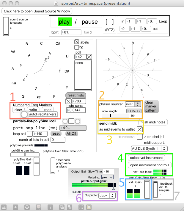
Figure 4.25: _spiroidArc+timespace.maxpat (annotated)
To get started with using this patch, the seven areas indicated in Figure 4.25 can be navigated in the given order, but there are many other ways in which the system can be configured and used. For ease of reference, a copy of the .png file that forms Figure 4.25 is included in the folder of the portfolio, along with the maxpat. Annotation to correspond to the indicated areas:
-
The controls added to the interface of the spiroidArc patch that pertain to the numbered frequency markers; see §(4.4.3.a) for details. Note, also, that input to the spiroidArc module patch can be provided via the 'Sound Source Window' which has the ADC and a sound file player as options; below the 'open' textbutton is a slide to set level for sending that source to the output (see annotation 6, below).
-
The 'phasor source' in the embedded time-space patch will default to being labeled as 'off', but it is actually set to receive phasor~ input from its inlet when the patch is loaded; the input signal, ramping from zero to one drives, drives the motion of now around the time-space representation which is here quantised to 16 steps, represented as the spokes on the GUI. The transport interface module – linking play / pause to the qwerty space bar – above the time-space module, gives access to the 'GlobalTransport' timing system of MaxMSP; the object connected to the input of the time-space is declared as phasor~ 1n @lock 1.
Using the same 'point with mouse and press a number key' method described for placing frequency markers on the spiroid-frequency-space, numbers can be placed on the spokes of the sequencer. As the time-space is traversed, each spoke is evaluated; if there is a marker on the current spoke, and if that maker currently has a valid midi-pitch value stored in the coll, then a midi note message is generated for that pitch. The length (duration) of the generated midi notes is set by the horizontal slider that is shown within annotation area two of Figure 4.25: the convention for note duration value naming that is native to MaxMSP is used here, but the duration in milliseconds for that value at the current tempo (bpm) is also displayed.
-
For the setup being described here, the midi note data is set to be sent 'as midievents to outlet' which is the format used by the vst~ object.
-
Select a suitable VST instrument to receive the midi note data; the pre-fade meter gives visual confirmation that audio is being generated.
-
Slider to set level of the audio signals coming from vst~ towards the output (with 'post-fade' metering).
-
The 'output to' option will default to 'off'; the other two options for this are 'dac~' and 'outlets' where the later is used in case of _spiroidArc+timespace.maxpat being embedded within another patch.
-
The final item of annotation here is the slider that sets level of gain for the audio output of vst~ to go to input of the spiroidArc patch for analysis and display. This feedback option allows for frequency markers to placed and moved on the spiroid-frequency-space GUI in response to the audio that they themselves contribute to the control of.
(4.4.3.d) Evaluation
In retrospect it is now thought that there is great potential for this type of spiroidArc and time-space pairing; within the context of this project, however, its focus of the generation of midi messages (originally targeting a hardware synthesizer, but demonstrated with a VST instrument) is somewhat removed from the aesthetic motivation of working closely with the soundmaking processes at the data level of processing in software systems.
The continued prevalence of midi, three decades on from its introduction (MIDI Manufacturers Association, 2013), is perhaps in part due to its encapsulation of the CMN paradigm, that has several centuries of influence on Western culture, and in which music is predominantly conceived of as events called notes. My work is founded on a conception of music as being existent in the process of soundmaking, and my focus is on the visual representation of sound in software during the act of composition. That focus has led to a process of soundmaking that seeks to integrate multiple layers of abstraction within the creative work; the spiroid-frequency-space concept provides representation of the frequency-domain throughout my continuing practice.